
JNXRFID · Know-how Series · Deployment Reality KH‑003
The Tunnel Reads the Pallet Next Door
Two adjacent read zones are wired, both are working, and stock from the neighbouring bay keeps appearing in your count. This is the most common consequence of specifying a reader by power instead of by zone geometry, and it is fixed in the physical layout rather than in the reader.
13 min read · Applies to UHF passive RFID · Multi-antenna tunnels, cabinets and portals · First edition, October 2026
Our portal reads stock from the adjacent bay and our cycle counts keep disagreeing with physically looking at the aisle. Both antennas test fine individually. What controls whether a read zone stops where it is supposed to stop?
A read zone has no wall. It is an energy field shaped by the antenna, the tag and the room together, and it does not end at the edge of your structure. When two zones are close enough, they overlap, and an overlapping pair reads the same pallet twice. The individual antennas are not faulty; they are each doing exactly what they were designed to do in a room that was never asked about them.
A read zone is not a boundary
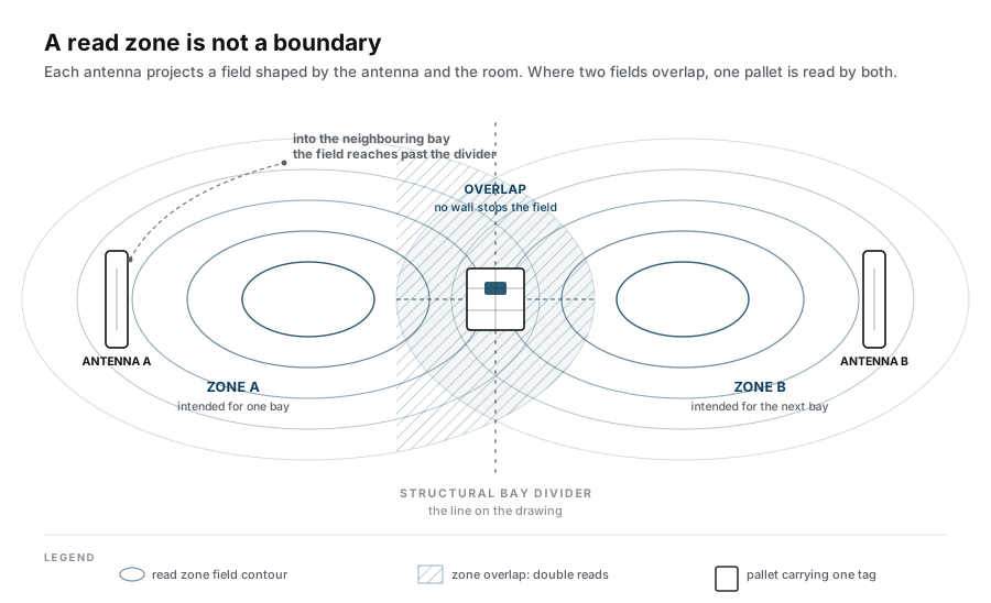
An RFID antenna does not project a rectangle that stops at a line. It projects a field whose shape depends on the antenna's own geometry, on what it is mounted to, and on everything conductive near it. Steel racking, a concrete wall and a pallet of liquid product each reshape that field in a different way, and none of them respect your drawing.
Two consequences follow, and both are routinely mistaken for reader defects:
- Zones bleed. A portal antenna intended to cover one pallet position reliably reaches past it, because the field spreads and then reflects off the structure around it.
- Zones interact. Two antennas running at once do not simply add two independent fields. Where the fields overlap, a tag in the overlap is read by both, and it is also read twice as often by either.
Why more power makes it worse
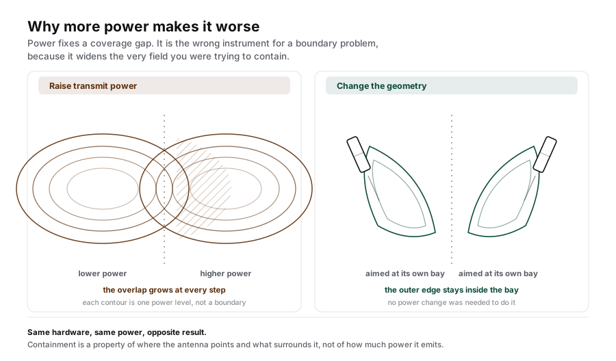
The instinct when a zone is too small is to raise transmit power. That instinct is correct for a coverage gap and wrong for a boundary problem, and the difference matters.
Raising power widens the zone in every direction at once. The unwanted reach grows by exactly the same proportion as the wanted reach. A zone that overlapped its neighbour by thirty centimetres before the change overlaps it by forty-five after it.
There is a second effect that is less obvious. In a reflective metal environment, higher power delivers more energy to tags you did not intend to read, which makes their replies stronger and easier to decode. The cross-reads do not merely become more frequent; they become more certain. Cross-reading therefore gets worse with power in a way that ordinary coverage loss does not, and a power increase can convert a working system into a failing one.
Test to run this week
Read the neighbouring bay's stock with both antennas active, then again with only one active at a time. If a pallet is read by both when both run, you have an overlap problem and no amount of reader configuration will remove it. If it is read by one antenna whether or not the other is running, you have a stray-coupling problem and shielding is the cheaper fix.
Geometry beats power
Because the boundary is a physical outcome, the effective controls are physical. In rough order of what usually works:
- Separate the antennas. Physical distance between two portal legs is the single most effective control, and it is free. A gap that looks generous on paper is often consumed by the reflective surfaces the portal is mounted to.
- Choose antenna polarisation deliberately. A linear antenna has a strong axis and a weak one. Orienting two adjacent antennas on perpendicular axes usually reduces mutual coupling more than any configuration change, because the field one antenna relies on is the field the other suppresses.
- Contain the zone physically. Absorbing material behind an antenna, or a metal shroud around the read area, trims the field without touching the powered budget. This is the standard technique in the smart-cabinet form factor, where the enclosure itself is part of the antenna design.
- Move the tag, not just the antenna. Tag position on the asset changes where the tag sits inside the field, and therefore how strongly it couples to the far antenna. Re-mounting a label is often cheaper than re-engineering a portal.
- Last, reduce power to the level the application actually requires. Running at the minimum that meets the coverage requirement is what keeps the zone small. Power is a ceiling setting, not a performance setting.
What session settings can and cannot do
Reader configuration is worth tuning, but it solves a different class of problem from the one described here, and confusing the two wastes a great deal of time.
| Control | What it actually changes | Does it fix cross-reading? |
|---|---|---|
| Transmit power | The outer reach of the field in all directions. | No. It widens the boundary. |
| Read session sensitivity | How weak a reply the reader will accept. | Partly. Raising it makes far tags decodable, which is the problem. |
| Tag population / target selection | Which tags the reader will report and in which order. | Only if the unwanted tags can be excluded by protocol rather than by field. |
| Antenna multiplexing order | Which antenna is powered and when. | Only if the two antennas are physically close enough to couple, where alternating them breaks the overlap window. |
The honest summary is that session settings can suppress a cross-read that already reaches the reader, but they cannot stop energy from arriving. Anything that requires the field not to reach a place has to be solved before the signal gets there.
A diagnostic sequence that finds the boundary
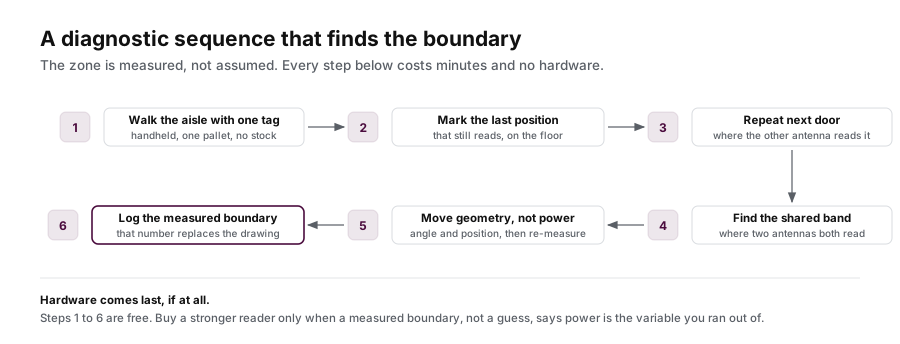
Cross-reading is diagnosed by moving one variable at a time, in this order, because the boundary is easiest to see when nothing else is moving.
| Step | What you do | What it tells you |
|---|---|---|
| 1 | Map the zone with the stock present but no tags on it, using a handheld at low power. | Shows the physical field shape, which is rarely symmetrical and rarely where the drawing says. |
| 2 | Place one known-good tag at the exact position where a cross-read is reported. | Confirms the cross-read is a field problem and not a data problem, such as a duplicate record. |
| 3 | Read that tag with only the far antenna powered. | Isolates whether the far antenna reaches it directly or only in combination. |
| 4 | Re-orient one antenna by ninety degrees and repeat. | Polarisation change is the cheapest large improvement available. |
| 5 | Measure the actual separation between antenna faces, not centre-to-centre on a drawing. | Mounting hardware frequently eats the gap the layout intended. |
| 6 | Only now, set power to the minimum that still meets the coverage requirement. | Now the number is derived from a measured requirement instead of from a datasheet maximum. |
What to measure instead of what to believe
| Measure | Why it matters |
|---|---|
| Cross-read rate at the zone boundary, with real stock | This is the defect. Everything else is a proxy for it. |
| Read rate at the far edge of the required coverage | Defines how much power you actually need, which sets how large the zone is. |
| Antenna-to-antenna separation as built | The single most common gap between design and reality. |
| Behaviour with both antennas active versus one | Distinguishes overlap from stray coupling, which have different fixes. |
| Whether the unwanted read is repeatable or intermittent | Intermittent cross-reads usually mean a marginal field shape, not a design fault. |
Each of these is cheap to collect and none of them requires the supplier to be in the room. A site that can report them is negotiating from measurements; a site that cannot is negotiating from a datasheet, and that asymmetry decides both the outcome and the price.
From diagnosis to specification
Turn the measured boundary into a specification
The sequence in this article produces four numbers: cross-read rate at the boundary, read rate at the far edge, the antenna separation as built, and the behaviour with one antenna versus two. Those four numbers are what a quotation should be based on.
- Measure the cross-read rate with real stock before changing any hardware.
- Fix the beam shape and the mounting points before you touch transmit power.
- Send the bay dimensions and the as-built separation; we will size the antenna and the reader to that boundary rather than to a datasheet maximum.